

How to Make Joystick Mounting Plates ...or, how I made mine |
 |
|
Problem: You're trying to upgrade the joysticks on your control panel and the new joysticks have a different mounting plate. Solution: Time for field modifications! |
|
by James McGovern - April 2006
Introduction
At the beginning of the year, when I published the Ultimarc Mag Stik review, I promised I would write a follow-up article describing how I made new joystick mounting plates in order to fit the Mag-Stiks to my existing and already drilled control panel.

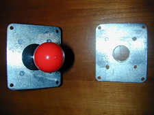
Mag-Stick disassembled
The existing panel, featuring a multi-williams layout, originally housed WICO 8-way, leaf-switch joysticks. The Ultimarc Mag-Stiks I intended to use came with joystick mounting plates that were not the same size as the WICO plates and I was faced with the decision to either re-drill my existing panel (and redo the artwork and redo the plexiglass overlay) or make new mounting plates for the Ultimarc upgrades.
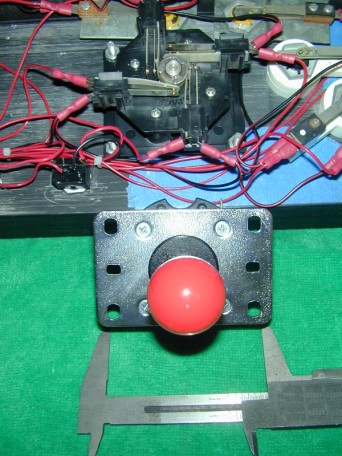
Realization: One of these things is not like the other
Obviously, the mounting plates were the way to go so I set out to find some metal stock to use for the plates. I trucked over to the local Home Depot and hit the hardware aisle where the bin of metal stock is located. After 15 minutes or so it became apparent that there was no metal stock thick enough to use for a mounting plate. Time to get creative.
Luckily I have a background in the trades and set my mind to work thinking what I had seen in my travels that may be found at a hardware store that could be used in this application. I needed something at least 3"x3" and around 1/8" thick or more. Cheap is good too.
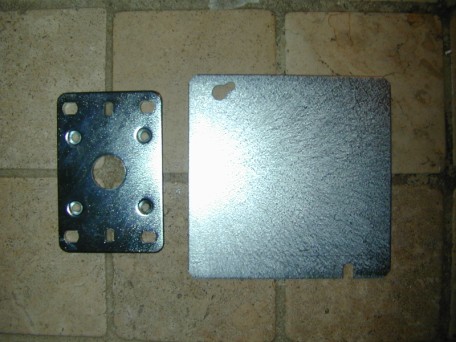
The Mag-Stick plate next to the electrical cover
The winner turned out to be this metal cover for a double-gang electrical box that is used to cover the box when it is used as a junction rather than to hold outlets or switches. The plates are thick, sturdy, and at about $0.45 each, the price was right!
Getting Started
Once I had the stock, the rest is just a matter of laying out the measurements correctly, making the appropriate cuts, and drilling in the right spots. Mostly...
At this stage I have to explain the sub-heading I included in the title above. You may have noticed I proudly announced that this article would detail, "How to Make Joystick Mounting Plates," but then I slipped in the qualifier, "...or, how I made mine." The reason for this is that like any new project, lessons are learned along the way.
.jpg)
The saw I used, you really need a table saw or chop saw
I do not have a vast background of experience in metalworking and sadly do not have a proper shop in which to work. I learned along the way and improvised where needed. I will try to help others to learn from the process and will point you towards what I think may be better ways to handle certain aspects of the operation.
Here is what I used -
- Double-gang metal electrical box cover
- 1/4" metal cutting drill bit
- 3/4" metal cutting hole saw
- Hand drill
- Circular Saw w/ metal cutting blade
- Belt sander
- Small C-clamp
- Pencil
- Paper
- Ruler
- Safety Goggles
Cutting the Problem Down to Size
For my first step I decided to cut the plates to size and match them to the footprint of the plates I needed to emulate, the WICO 8-way leaf-switch plates. To do this I simply disassembled one of the WICO joysticks and laid the mounting plate face-down on the metal blanks I picked up at the hardware store. After tracing I was ready to cut.
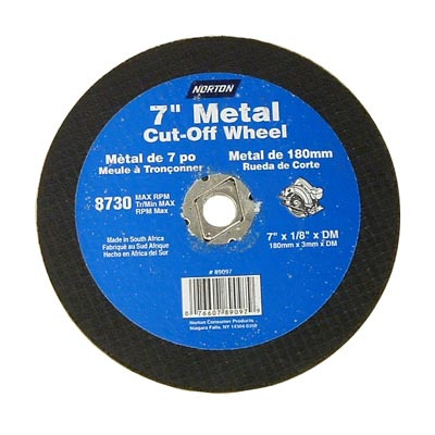
You will need to use a metal cut-off blade like this
I used my C-clamp to secure the plate to a sturdy surface and then cut the plates to size using the circular saw outfitted with the metal cutting blade. Make sure to wear your goggles when cutting these plates as the sparks will fly.
I would definitely to this differently next time around. The electrical plates I used are only about 5"x5" in length and width. When clamped to a surface, this leaves very little if any surface left for cutting, especially with a circular saw. I had to hold the guard back on the saw and cut the plates in mid-air as they hung off the surface. Not smart folks.
A better way to do this is to use a table saw or even a chop saw. I suggest screwing the plate to a piece of wood that is easier to handle then running that through the table saw or chop saw so your hands are far away from the cutting. You will also get a cleaner and straighter cut, something I had to compromise on due to my dumb-devil stunt with the circular saw.
After making the cuts use your belt sander to clean up the edges and remove any burs from the plates. You can also use a metal file for this or in a pinch drag them across a concrete surface.
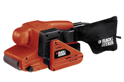
My trusty Black & Decker
Another lesson learned here is that I would have added about 1/8" to the width and to the length of the new plates. If you have the room on your control panel, leave some leeway to ensure you have enough room for the holes you are about to drill in the plates.
Also, I got a bit overzealous with the belt sander and decided to round the corners of the plates at this stage. On a couple corners I took too much off and it made it harder to drill later and had me worried I might split the corner. Leave a little extra stock and don't round your corners until after you are done drilling.
Drilling the Plate Mounting Holes
Drill the holes and your done! No problem. Ok, this took a little longer than I suspected. Mostly because I started to realize that this stuff really did have to line up in order to work correctly. I am used to working in with wood, having a carpentry and cabinet-making background, you get some leeway with that material. Here if things don't line up, it just wont work.
I placed the WICO plates back onto the newly cut plates and lined up the edges in order to trace the mounting holes. We are just matching the mounting points on the control panel with these plates.
Once traced out I was set to drill. Again I used the C-clamp to hold the plates down and went to town with my cordless drill and a 1/4" metal cutting bit.
I trusted in pressure and a steady hand to line up my drill with the holes I needed to drill. Next time I will take additional steps to ensure I get a clean hole exactly where I want it. The problem is that the bit likes to travel around the surface of the metal making it hard to keep the bit true.
Next time around I will either use a punch to mark the center of the hole and keep the bit true, or better yet employ a proper drill press making sure the plates are good and secure.
Drilling the Center Holes
Next up was the center hole and for this I used a 3/4" metal cutting hole saw. Again, just place the WICO plate on the new metal plate and trace out the hole. Mark your center by drawing an "X" through the center of the circle you place on the plate. The disclaimer above applies here too, I would punch the center and or use a drill press if at all possible as this bit liked to travel as well.
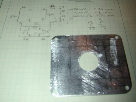
Rough edge on the center hole, but it is hidden when installed
Another note here, I was in a time-crunch and realized all too late that the pilot bit used in the center of the hole saw was slightly bent. I am ashamed to say it but I went full steam ahead anyway. this resulted in an oddly shaped hole that could have been much cleaner with the right tool. Luckily this is not seen at all when you are finished, so it is only there for me to worry about.
Drilling the Joystick Mounting Holes
The Mag-Stik mounting holes out to be trickier than I thought they would be to get lined up properly. I never made a template of each mounting plate and instead relied on being able to trace out the patterns needed from the different plates. This was a pain with the Mag-Stik plates at this stage as the only point of reference at this stage was the center hole I cut from the WICO plate.
Remember, now I need to transfer and cut the four holes from the Mag-Stik plate, used to actually mount the joystick to the plate. If the four mounting holes are not lined up with the plate-mounting holes, the stick's switches will be off and game play will be affected. Time for pencil and paper.
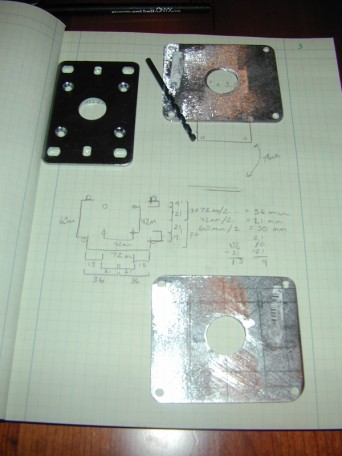
Measure, shmeasure ... get a template
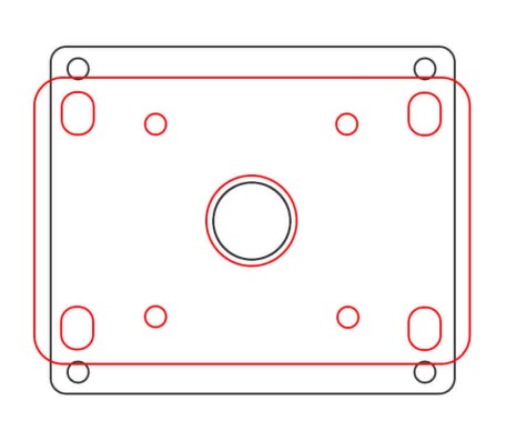
Now I'm not going to go into the cavalcade of measurements and sketches you see above. They worked, but they did not work well and frankly there is a better way. Now that I have had some time to reflect on the process, what was really needed was a template showing both plates and the locations of the appropriate cuts. I have since created that template and include it now for your use.
A template for the WICO joystick - Click for a scale image (PDF)
Drilling the Joystick Mounting Holes
At this stage the only thing left was to re-assemble the joysticks and install them into the control panel.
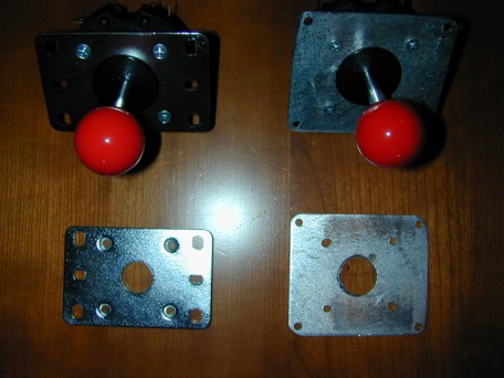
The completed plates
Important consideration here depending on your needs and preferences. As you can see by the picture below, the screws that are used to mount the Mag-Stik to its mounting plate are countersink screws. I did not countersink the holes in my new plates as I thought I was being slick. I wanted to create a small gap so the dust protectors could be located under the control panel and leaving these screws protruding out of the top of the plate would afford me that ability.
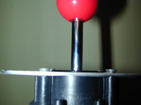
It would have worked out great...
Like many well-laid plans, this was not to be. The way the ball top shafts for the Mag-Stik are made, you cannot take the dust cover off in order to relocate it under the panel. I had to settle for keeping them on top, not my preference but it worked ok and looked better than I originally thought it might.
I left the screw heads they way they were, protruding from the top of the plate as they did not cause any mounting issues left that way.
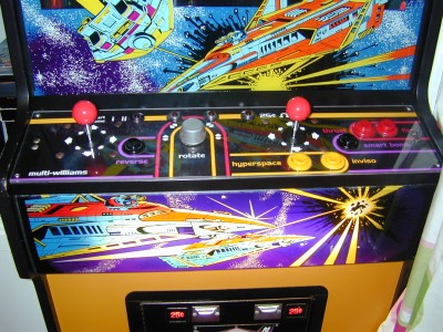
Dust covers on top, but it looks good
Well, here they are, installed and ready to go. The final product looked great and all-in-all the operation was a success. Next time around I will be sure to employ safer methods when cutting and drilling the plates, with an upgrade to my tools that is. A drill press would have gone a long way in making the process easier and more precise, if you have access to one I highly recommend you use it when drilling.
RetroBlast Review - Ultimarc Mag-Stick Joysticks
|

